| a multi-stage wave guide oscillator in VHDL | |||
| DSP Module | This page shows another implementation of my multi-stage-feedback delay. In this case it uses extreme short delays and thus realizes a wave guide oscillator. It works with similar methods as the well known Karplus-Strong-Algorithm. It is an update of the first version which initially had been implemented in my Chameleon Synthesizer using C-Language at that point of time and later had been ported to VHDL. Hardware While the first version was running in a Spartan device this one was ported to Altera Cyclone using both the Gleichmann HPE Mini and my new Altera Cylone PCB: 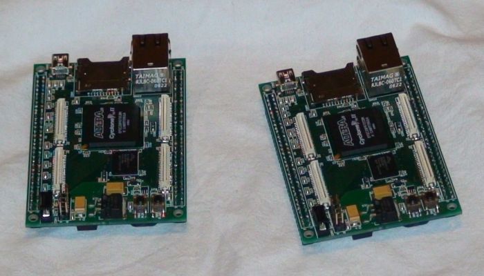 Block Diagram of the Oscillator 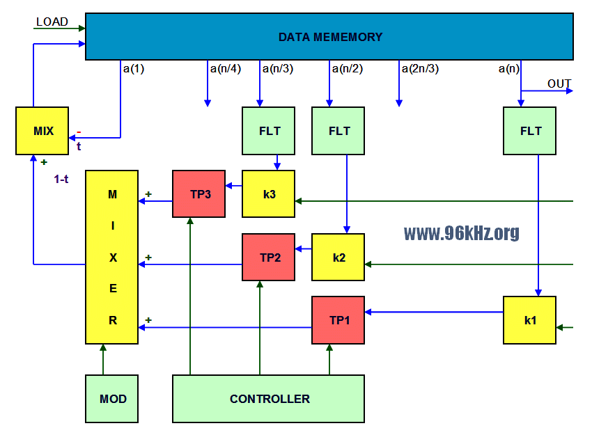 Unlike in my first version of the multi delay oscillator using wave guiding this way, here 3 or more feedback loops are used to drive the harmonics of the base frequency back into the circuit, coming much closer to the behaviour of the focussed string instruments. As is well known, the odd integer harmonics of the fundamental frequency give stringed instruments their characteristic timbre. It is also crucial that these do not fit perfectly within the wavelength; this can be achieved by selecting the appropriate tapping point and/or interpolation of the length. The feedback signals are scaled adequately and added to the existing mix with defined post scaling to achive a simple IIR-Filter ("MIX") that way that the overall energy in the cirucit slowly disappears in a controlled way. By using dedicated equalizers in the paths, also the harmonics can be even controlled in a more detailled way. IIR filters are generally used to attenuate the high frequencies. All filters are controlled via modifiers (essentially a type of LFO, which I use in my synthesiser to adjust parameters in real time). Here, the mixer is controlled intuitively to give the sounds more of a live feeling. More than 3 stages require lower feedback ratios in order to create a more dedidacted behavior of the harmonics. Note that this requires a very precise interpolation in most cases. One must not overlook that after each loop "the harmonics of the harmonics" will be introduced into the signal. Practically a 1/4 and an 1/6 loop showed good results when applied slightly however a third and a fith should be more suitable for the classical guitar sound. Regarding the initial wave to be fed into the RAM, a multi harmonic music pulse appears most effective, which already describes the intended base frequency. Therefore the pulses have either to be prepared in a RAM when focussing a DSP system or must be resampled accordingly. For my FPGA solution I found a very simple way to to this by simply using one frequency for filling and another one for reading which is a feature of modern block RAMs. The design works with 96kHz sample frequency and almost 50MHz FPGA clock frequency (96.000 x 64) offering 512-times oversampling. This is a great advantage when it comes to an efficient sub sample filtering required for the interpolation. When 4 paths are used, 128 times oversampling can be applied while all required filter functions can be calculated in sequence. Example Waves The following curves from the FPGA-Oscilloscope have been copied together for two cases showing 5 points of time after a period of one second. The cyan-green waves at the left side show the behaviour of a simple feedback. The right sequence shows the introduction (or the maintenance!) of the third harmonic, which grabs a part of the inital energy of the wave. After 5 sec the simple circuits presents a sine wave, where the third harmonic is still present in the right example. 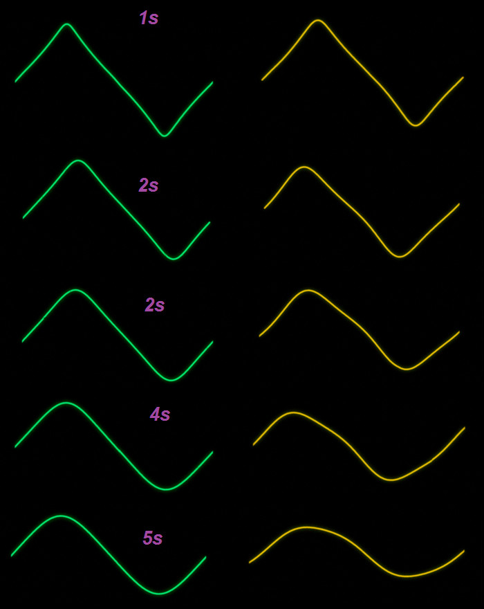 Examples with more feedback Using more feedback of the third harmonic and a clean phase constellation the signal rapidly progresses to a triangle. That in fact is a non natural behaviour which is in return suitable for new sound to be used in electronic music. 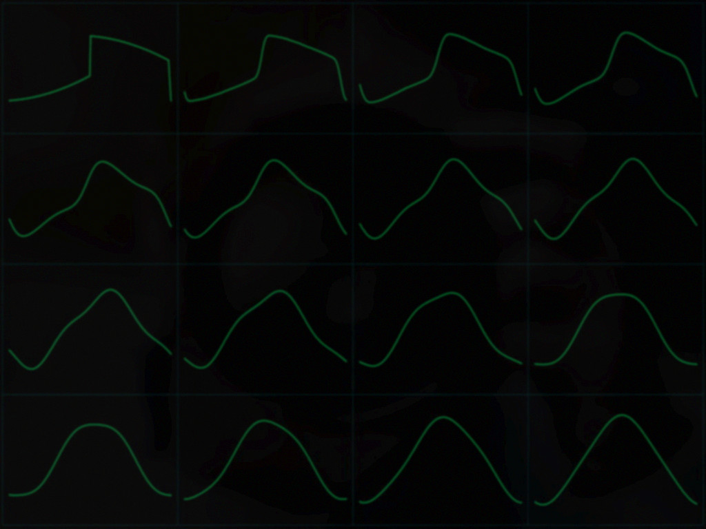 This also is the case when using the 5th harmonic a bit more and a different start pulse 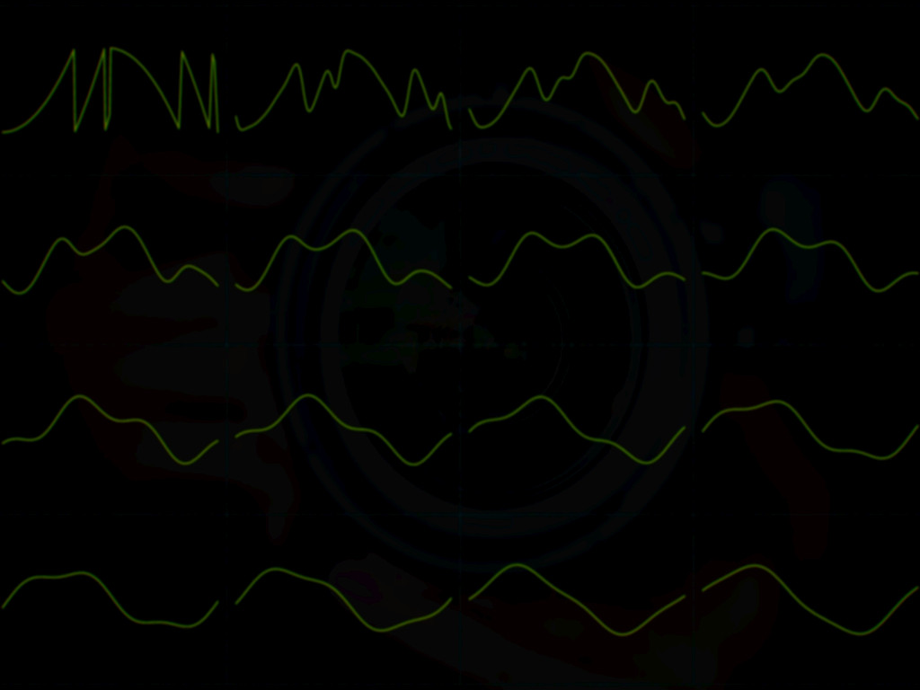 Remark As formerly stated, this approach is a bit similar to the Method patented by Karplus and Strong from 1987. In order not to violate this, a trick can be used: One undersamples the outgoing data stream slightly and truncates the delay appropriately so that the resulting feedback pitches correspond. This creates a de facto band limit without using an explicit lowpass so the filters can be partly left away. See the former circuit for this. Addendum 2007: The patent of Karplus / Strong has most probably expired. Read more about the former Version multi delay oscillator. Read some general information about the function of the K-S-Algorithm. Read more about the platform here: Gleichmann HPE Mini |
||
|
Altera Cyclone II FPGA
|
|||
|
96 kHz Audio DSP |
|||
|
|
|||
© Dipl.-Ing. Jürgen Schuhmacher 2007