| 96 kHz.org |
| Advanced Audio Recording |
|
A Virtual Analog Oscillator in VHDL This page shows the basics of virtual analog modeling with digital equations and a concept to realize it in an PLD.
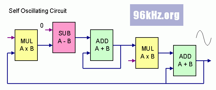
a self oscillating circuit An easy oscillator can be built using two accumulators with a feedback path and scaled factors using the subsequent logic elements:
The adders accumulate the incoming scaled values and thus act as integrators. While the first accumulated value acts as a kind of speed, the second one is the position and the inverted acceleration. The resulting equations for this case are a classical differential equation system and lead to a sine wave - the known solution for mechanical and electrical systems which oscillate. To use this directly in C language it is necessary to use the REAL type for the variables when performing the calculation. For Verilog and VHDL this has to be treated in a different way:
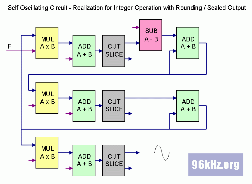
virtual oscillating circuit in integer INTEGER calculation is used in this case and precise rounding techniques will have to be applied to get a sufficient accuracy and avoid issues caused by vector cropping:
With this circuit a permanently running oscillator is realized if feedback factors are set properly to get a stable system. The resulting frequency and amplitude are implicitly given and can be indirectly controlled in that way, that the multiplier values are changed. To switch it on or modify the output level, the final multiplier stage is used as a gate. It also compensates the variation of the amplitude with the frequency. The detailed values including a certain offset for both velocity and amplitude will depend on the starting conditions.
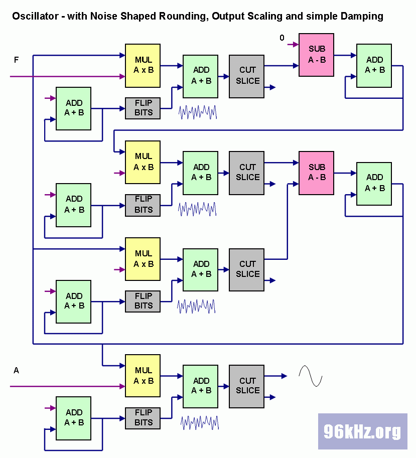
from digital to analog Although the above stage of the oscillator works fine, it is still far way from being analog. Dirt effects will have to be added in order to obtain a more realistic behavior whereby one is most essential: Real circuits will always come with loss effects which at first glance seem to be a problem but are not when having a closer look at this issue: Loss will surprisingly add stability to the circuit and also solve the offset problem. In the subsequent version of the circuit, noise is added to achieve analog dirt and a noise shaped rounding method to lower coarseness. Also another feedback line is added by looping back the volume level which performs first order damping and BIAS removal.
The noise shaping here is done with a very easy noise generator using a binary counter together with the bit flip method. Better results can be achieved when using counters with non binary lengths and optimized progressing steps.
Read more about Virtual Analog Modeling
|
| © 2002 J.S. |


