| 96 kHz.org |
| Advanced Audio Recording |
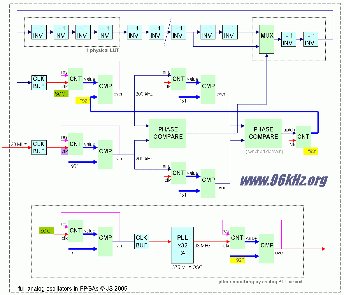
A real analog synthesizer with Altera FPGA This page shows a way to create an analog like music synthesizer using the analog features of a FPGA. Being a dedicated digital circuit in the first place, FPGAs are usually programed that way that the logical function is defined and translated into time discrete behavior by operating with clocked circuits using the available structures in the FPGA. This makes the logical function independent from switching and timing characteristics thus analog behavior of the FPGA caused by effects like rise times, delays and incoherent busses are shunned as best as possible. Giving the analog behavior a chance, I created an oscillator based synthesis module which works similar to classical digital organs: Typically here is one high frequency oscillator present, driving the whole sound synthesis unit. Low frequencies required for the final sound creation are derived from this master oscillator by frequency division. Therefore a self oscillating circuit in the FPGA adding some frequency dividers subsequently should be the first idea but showed up with some issues. To understand the problems, a more detailed view on FPGAs is necessary: Self oscillating circuits are not a standard type of element available in FPGAs since they are only required for special applications like self starting reset topologies and internal signal analysis with logic analyzers when there is no external clock. These functions have to be created manually by e.g. putting an odd number of LUTs into a chain with back coupling the last one's output to the first one's input. Depending on the chain length, switching characteristics and outer influences like temperature and possibly also radio frequency one will get a more or less stable oscillator with a non dedicated unknown frequency. Short chains of 5-7 LUTs lead to 100MHz - 300MHz in current FPGAs like Spartan or Cyclone. Once having created such an OSC, the whole circuit which is driven by it, runs on this frequency. From that on it should have been possible to create the desired frequencies for sound synthesis if the frequency is known well enough to set up the dividers. Because of the first unknown frequency which will be FPGA dependent, a kind of PLL will have to be instantiated to softly synch to a given dedicated frequency from the outside. The first approach is to apply a digital oscillator of a known frequency to a pin of the FPGA and sample it's input to afterwards toggle the oscillators output signal. This commonly used technique works best to synch the data frequency of any clock domain to a foreign domain in order to maintain the same throughput in the long run. But we need something different: The system frequency has to be changed so the LUT chain has to be affected directly. The idea was to create a switchable chain of two different lengths and find out if the resulting frequency is to low or to high and the adjust it dynamically. Therefore a self oscillating PLL-like circuit is created using a local frequency divider with adjustable division parameter is used. The strategy is, that the divider is dynamically controlled that way, that the division result creates approximately the frequency given at the input pin. The phase of the pin is observed and if the inner clock edge comes too late, the self oscillation clock generator (SOC) is accelerated by using the short chain. If the phase delay still rises, the devisor value is decreased and vice versa. This first leads to the fact, that the divider value is adjusted to nearly any incoming clock frequency and once reached this state, only the chain length toggles to keep the inner OSC in phase. To work properly the chain length has to by large enough that the switching does not affect to clock edge wave running though the circuit and divider adjustment has to be at least 10-100 times slower, so it will take some time before the clock is totally synched - possible up to a second or more. But this should not bother us since it happens only once during start up.
In the first system created with a current Cyclone 2 FPGA, the internal OSC was running freely on 140-180MHz when not synched. The synched frequency was measured with 112 MHz and a resulting divider of 12 for the 10 MHz synchronization clock applied from to outside, which seemed logical when we take into account, that the additional combinatorial and gate in between the chain increases delay. Because of a stability issue in the divider regulation, I decided to decrease the sync frequency. The second approach was to use a lower frequency of only 1MHz/32 (derived by internal division) for the divider adjustment and the full frequency for edge alignment. I also enlarged the length of the LUT chain leading to only 93 MHz OSC frequency but a stable divider of 92 for (n -1).
The problem now was, that 1MHz is a bit too slow to appropriately calculate the required dividers for the music frequencies especially for the 44,1kHz or 48kHz required for CD sound. It is also too slow to feed internal FPGA-PLL to derive a higher frequency to drive the subsequent parts of the circuit. A PLL was introduced to remove the jitter of the SOC the analog way, because edge adjustment is done smoothly by such a device, but driving a PLL directly from the jittering SOC was impossibly. So the next step was to do a kind of manual decimation filtering a adding a gray counter which toggles the frequency by ratio 1:8 and soothes the jitter enough to feed the PLL with a stable input frequency and still stay above 11 MHz which is the lower limit of these Altera Cyclone 2 devices. For other FPGAs of the same type, this structure will work anyway, but for different FPGAs one might have to change to 1:8 ratio eventually. Anyway, the PLL rises the internal frequency by ratio 16 and the following divider which of course has to be exactly the number 464 shown above, will create the know frequency of 200 kHz x 16 = 3,2400 kHz which is suitable to drive digital circuits again. Starting from the 3,2 MHz, it is possible to calculate the 12 soft dividers for the music frequencies C5 to C6 which are used in this synthesizer. The lower octaves are obtained by simple cascaded division of 1:2 then. Also it is possible to use individual counters for all frequencies C2 .. C6 instead of using octave shifting.
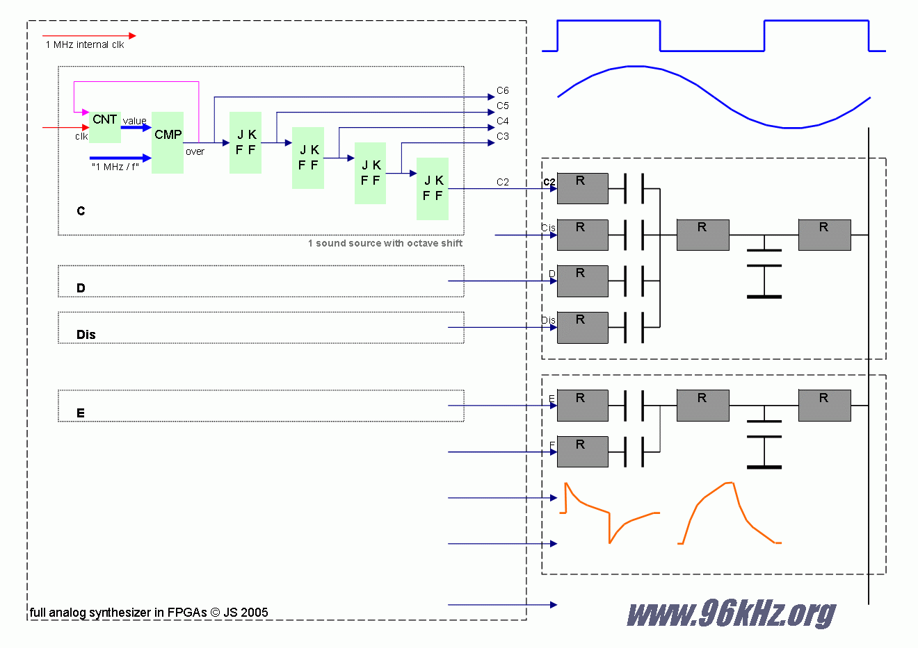
From this point, we have our musical frequencies from C2 to C6 ready to use, but there is again another new issue: The circuit produces the desired analog behavior very well, but frequency movement is totally the same for all music frequencies. So the next idea was to instantiate 11 different SOCs running with also different chain lengths not to synch to each other which usually happens with such structures, according to my observation. 12 SOCs require also 11 PLLs which are not present in this device, so in one version the number of PLLs were limited to 6, when spreading to synthesizer over 3 FPGAs (I do not have more of this type present currently) and were totally left away in a test version. This issue should not be a big thing since newer FPGAs in future will most probably offer enough PLLs internally. Now, it is time to create waves from the OSCs, but how can waves be created "the analog way"? A commonly used strategy is to take a counter controlled by the OSC, make a virtual phase from out of it and then read sine wave values from a lookup table, using the phase as the address. This method is known as direct digital synthesis (DDS) and works fine for digital synthesis systems. From my feeling this is not suitable for an analog design, because tables have to be very large and values must be interpolated very well in order to achieve good results. Phase jitter is introduced though because of the limited length of the sine wave table. For our analog synthesis, we do it easier, better and more dirty: Whenever a counter of the 12 primary dividers or one of the derived frequencies toggles, we have a full square wave already present. Phase offsets and modulation can be easily be applied by adding an initial value to the counters or change them with more then +1/-1 with each clock cycle. The dividers' outputs are routed to 49 external pins, where analog circuits is attached acting as band width filters emphasizing the particular frequency. They outputs are summed up at this point. In a simplified version it was tried to group some of the outputs and use only a reduced number of bandwidth-limiters which worked also properly.
Estimating
that the circuit operates well, there is only low jitter in the self
running oscillators of about 5% when watching at one period with a
switch of the chain length. (It is 19/21 in this case) Because of
the division performed by the global divider, the 1MHz clock shows
only 1% jitter in maximum according to measurements done with Altera
SignalTAP logic analyzer. This also meets theoretical equations
estimating 0,7% in the average. Following the signal path, there
will be a further reduction of at least a ratio 200 for high output
frequency which has a low divider only. At the digital square output
a jitter of less than 0,01% is measured with an oscilloscope.
Simultaneous switching of an adjacent output has the double effect.
So it can be assumed that there is no unintended phase activity. The
one and only effect is the slow and alternating drift of the phase
which is introduced by the 1MHz based direction update in the long
run. The function behaves as a PCM based switch slowly and smoothly
following the drift of the input source. For the operation mode with
independent oscillators there will be always coincidental and
unpredictable phase relations between two voices which makes the
sound very natural and might be also used for primary OSC-creation
in
VAM-synthesis read the former article Analog Synthesizer with PLD
|
| © 2005 - Jürgen Schuhmacher |

