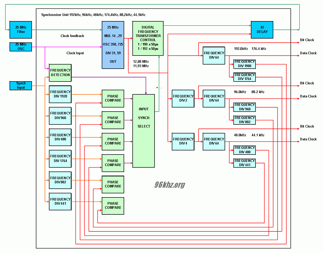
| block diagram of a frequency converter in an FPGA | |||
|
Frequency Converter Sample Rate Converter |
Synchronisation Unit  g this dynamically it is possible to change a given clock frequency by only a small percentages. With this circuit it is possible to generate any of the desired audio frequencies like 44100Hz, 88200Hz and 176400Hz from any of the given input frequencies like 96000Hz and common 48000Hz. Also the new 192000Hz planned for future audio systems is possible. With two units in parallel it is possible to do this vice versa. Unlike manual adjustment pf the target phase by controller adding delays to the signal, a PLL with explicit clock fedback is use to generate the two different master frequencies 12,8 / 11,3 MHz. Finetuning is performed by frequency transformation circuit though. Resampling is performed with one ore two resampling units shown below:
Resampler Unit
|
||
|
Full
Synchronized Operation 44,1 kHz 48 kHz 88,2 kHz 96 kHz 176,4 kHz 192 kHz |
|||
| 96
kHz Audio DSP |
|||
|
|
|||
© Dipl-Ing. Juergen Schuhmacher 2008
