| a DSD - cross clock domain resampler in VHDL | |||
|
Frequency Converter Sample Rate Converter DSD Mixer |
DSD-Resampling Module Since the DSD-format prevents direct
mixing, the signal must first be converted to, for example,
PCM. The conversion process involves what is known as decimation
of the high-frequency data into an intermediate format of equally
high resolution, with no loss of information. This intermediate
signal could then be summed to feed a DSD converter. However,
since the connected devices are not compatible and do not have
the same frequency response, a sampling rate adjustment must
also be performed. 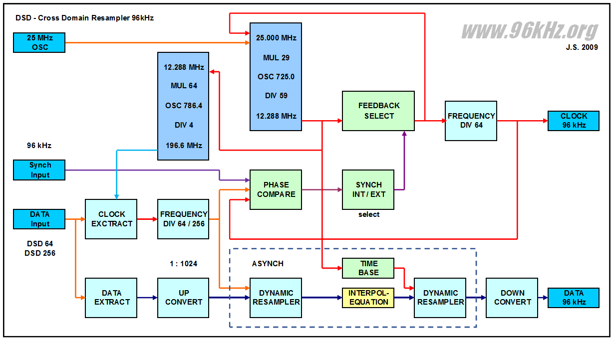 g this dynamically it is possible to change a given clock frequency by only a small percentages. Using the special 29/59 ratio for the MUL/DIV configuration a nearly perfect S/PDIF clock of 64 x 96kHz is obtained from any normal 25 MHz clock oscillator. Using common digital up conversion and filtering with a special progressive technique an equation is continously generated which represents the current signal state of the given time period. Taking the new time base on the right side of the resampling unit into account, a new value is calculated from the interpolating equation.
Read about the detailled function of
the circuit in the article about the
Resampler |
||
|
Full Synchronized Operation 96 kHz optimized |
|||
|
96 kHz Audio DSP |
|||
|
|
|||
© Sound of L.A. Music Productions 2009