| capacitive music keyboard | |||
|
Audio DSP |
This project shows my recent music keyboard using capacitive sensor pads: PCB Hardware EAGLE Design  Top and Bottom of the PCB design Each pad is touched from the component side (red) receiving a special signal from the bottom side (blue). The amount of present frequencies in the received signal determines the detailed position of the finger against a normalised key position. Noise analysis has to be performed to achieve this. The position information can be used to drive a vibrato channel in a MIDI stream. Design has been done with Cadsoft Eagle. FPGA Design 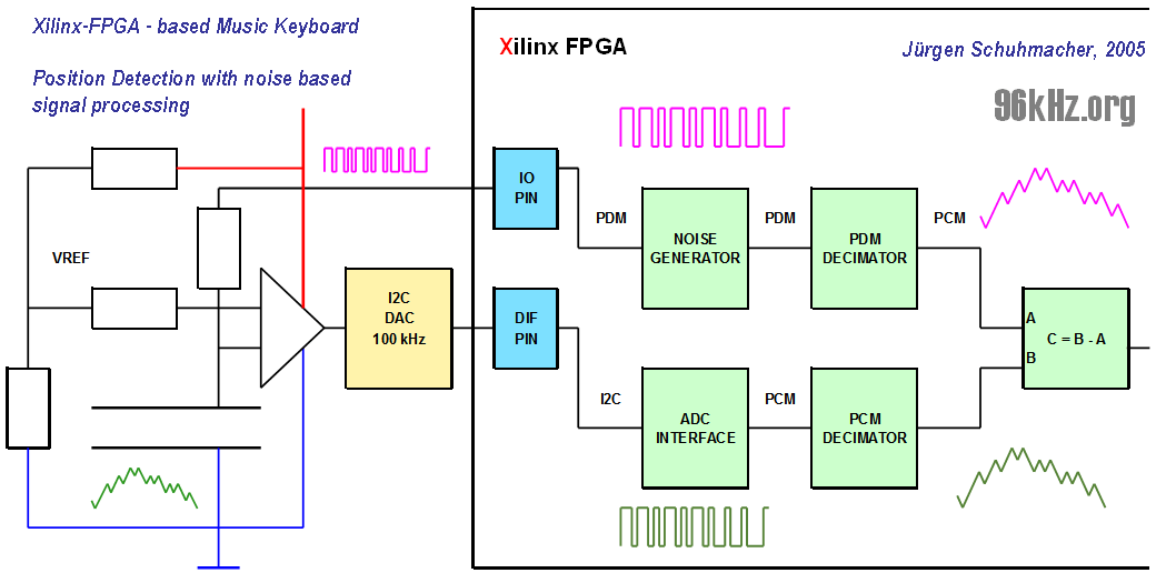 FPGA-design of the circuit driver A LFSR-design is used to generate dedicated noise for both the capacitive key and the signal used as a reference for the internal comparator. The ADC feeds the FPGA by I2C with the overcoupled signal. Decimation and filtering is performed to prepare the signals for comparison. The stage subtracts both signals from each other thus sorting out the information of pressure change for the subsequent processing module. That part of the ciruit works similar as the PDM-ADC. The finger changes the electrical field close the key and changes the amplitude of the noise when it is close to the sensor and when pressure is applied. The position of the finger emphasises certain frequencies coming from the noise. The information of position is extracted from the phase information of these frequencies, by a gravity point analysis looking for the highest amplitude. FPGA Hardware Spartan 3E - System 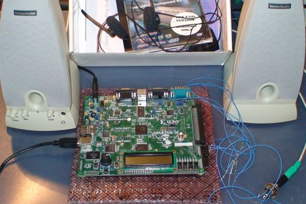 A Xilinx Spartan 3E 500 - KIT A current Xilinx-FPGA programed with VHDL is used to implement the design. With the given resources 24 channels can be driven a the same time offering the chance to run 3 octaves. For more information about the idea, see the former version Info: The idea was taken from methods of our Institute for Metrology Engineering at University Siegen, Germany. It dealed with an application to measure small changes of a capacities, presented at the MESSCOMP96 meeting in Wiesbaden. I realised this in a first test board: Details can be found here: First Version / Invention |
||
|
|
|||
© Dipl.-Ing. Jürgen Schuhmacher 2005